Reading a car stereo wiring diagram doesn’t have to be confusing. This guide breaks down symbols, wire colors, and connections so you can install or troubleshoot your car audio system with confidence. Follow along to master wiring diagrams like a pro.
Key Takeaways
- Understand common symbols: Learn to identify ground, power, speaker, and signal wires using standard diagram icons.
- Decode wire colors: Most car stereos use color-coded wires—red for ignition, yellow for constant power, black for ground.
- Identify connector types: Recognize ISO, DIN, and proprietary harnesses to match your stereo and vehicle.
- Use a multimeter for accuracy: Test wires before connecting to avoid damage or incorrect installations.
- Follow polarity carefully: Correct speaker wire polarity ensures proper sound quality and phase alignment.
- Refer to your vehicle manual: Factory wiring diagrams vary by make and model—always double-check specifications.
- Practice safety first: Disconnect the battery before working on any electrical system to prevent shocks or shorts.
Introduction: Why Understanding Car Stereo Wiring Diagrams Matters
Installing a new car stereo or troubleshooting an audio issue? You’ll likely encounter a wiring diagram. These diagrams look like a maze of lines and symbols at first, but once you know how to read them, they become your best friend. Whether you’re upgrading your factory radio, adding amplifiers, or fixing a blown speaker, understanding how to read a car stereo wiring diagram saves time, prevents damage, and ensures your system works perfectly.
This guide will walk you through everything you need to know—from decoding wire colors to identifying connectors and testing circuits. By the end, you’ll be able to confidently interpret any car stereo wiring diagram and complete your installation safely and correctly.
Step 1: Gather the Right Tools and Resources
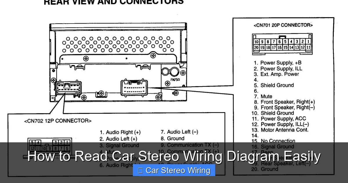
Visual guide about How to Read Car Stereo Wiring Diagram Easily
Image source: i2.wp.com
Before diving into the diagram, make sure you have the right tools and information.
Essential Tools
- Multimeter: Used to test voltage, continuity, and resistance. Crucial for verifying wire functions.
- Wire strippers and crimpers: For preparing and connecting wires securely.
- Electrical tape or heat shrink tubing: To insulate connections and prevent shorts.
- Trim removal tools: Help remove dashboard panels without damaging clips or finishes.
Important Resources
- Vehicle owner’s manual: Contains factory wiring details specific to your car.
- Car stereo manual: Includes the wiring diagram for your head unit.
- Online databases: Websites like Crutchfield, Sonic Electronix, or forums often provide model-specific diagrams.
Having these on hand prevents guesswork and reduces the risk of mistakes.
Step 2: Understand the Basics of Wiring Diagram Symbols
Wiring diagrams use standardized symbols to represent electrical components. Learning these makes reading any diagram much easier.
Common Symbols You’ll See
- Straight lines: Represent wires or conductors.
- Zigzag lines: Indicate resistors or speakers.
- Circles with “+” or “–”: Show power sources or battery connections.
- Ground symbol (⏚): A triangle or horizontal lines pointing down—this is the ground connection.
- Dots at wire intersections: Mean wires are connected. No dot? They just cross without touching.
For example, a speaker might be shown as a zigzag line between two wires labeled “Front Left +” and “Front Left –”. This tells you which wires go to that speaker.
Color Coding Standards
Most aftermarket car stereos follow a universal color code. Here’s a quick reference:
- Yellow: Constant 12V power (connects to battery)
- Red: Switched 12V power (turns on with ignition)
- Black: Ground (connects to chassis or battery negative)
- Orange: Illumination or dimmer wire (controls display brightness)
- Blue/White: Remote turn-on for amplifiers or antennas
- Speaker wires: Usually paired in colors like white, gray, green, and purple (with stripes or solid for + and –)
Note: Factory wiring may differ. Always verify with a multimeter or your vehicle’s diagram.
Step 3: Locate and Identify the Wiring Harness
The wiring harness is the bundle of wires connecting your stereo to the car’s electrical system. Most modern cars use a standardized connector.
Types of Harnesses
- ISO 10487: Common in European and Asian vehicles. Has a 16-pin connector for audio and a 6-pin for power/control.
- DIN connectors: Older standard, still found in some cars. Larger and less compact.
- Proprietary harnesses: Used by brands like Ford, GM, or Toyota. May require an adapter.
Using an Adapter Harness
An adapter harness bridges your new stereo to the factory wiring. It’s color-coded to match aftermarket standards, making installation plug-and-play.
For example, if your car has a factory harness with a blue wire for antenna power, the adapter will label it “ANT” or “Blue/White” to match your stereo’s input.
Always match the adapter to your car’s make, model, and year. Buying the wrong one can lead to missing functions or damage.
Step 4: Match Wires Between Stereo and Harness
Now it’s time to connect the stereo to the car. Use the wiring diagram to match each wire correctly.
Power and Ground Wires
- Yellow (constant 12V): Connects to the car’s battery via the harness. Keeps memory settings alive.
- Red (switched 12V): Powers the stereo when the key is on. Turns the unit off when the car is off.
- Black (ground): Must have a solid connection to the car’s metal frame. Poor grounding causes noise or no sound.
Speaker Wires
Each speaker has a positive (+) and negative (–) wire. Matching polarity is essential:
- Front Left: White (often with a stripe for +)
- Front Right: Gray
- Rear Left: Green
- Rear Right: Purple
Reversing polarity makes speakers play out of phase, reducing bass and sound quality.
Control and Accessory Wires
- Orange: Connects to the dashboard lighting circuit. Dims the stereo screen at night.
- Blue/White: Sends a signal to turn on external amps or power antennas.
- Pink: Sometimes used for vehicle speed signal (for navigation systems).
Not all stereos use every wire. Check your manual to see which ones are needed.
Step 5: Test Wires with a Multimeter
Never assume a wire’s function based on color alone—factory wiring varies. Use a multimeter to confirm.
How to Test for Power
- Set the multimeter to DC voltage (20V range).
- Touch the black probe to a known ground (like the car chassis).
- Touch the red probe to the wire in question.
- Turn the ignition on. A reading of 12–14V means it’s a power wire.
How to Test for Ground
- Set the multimeter to continuity or resistance (Ω).
- Touch one probe to the wire, the other to the car’s metal frame.
- A beep or near-zero reading confirms a good ground.
How to Test Speaker Wires
- Set the multimeter to resistance (Ω).
- Touch probes to two speaker wires.
- A reading of 2–8 ohms indicates a speaker circuit.
This step prevents connecting power to a speaker wire or vice versa—common mistakes that blow fuses or damage equipment.
Step 6: Connect and Secure the Wiring
Once you’ve identified and tested all wires, it’s time to connect them.
Twist and Crimp Method
- Strip about 1/2 inch of insulation from each wire.
- Twist the exposed strands together.
- Use crimp connectors or solder to join stereo and harness wires.
- Cover with electrical tape or heat shrink tubing.
Avoid twisting wires by hand and leaving them exposed—this can cause shorts or loose connections.
Using a Wiring Harness Adapter
If you’re using an adapter, simply plug the harness into the car’s factory connector and match the colored wires to your stereo. No cutting or splicing needed.
This method is safer, reversible, and ideal for beginners.
Step 7: Reassemble and Test the System
After wiring, carefully reinstall the stereo and dashboard panels.
Power On and Check Functions
- Reconnect the car battery.
- Turn on the stereo. Check for sound, display, and controls.
- Test all speakers—front, rear, left, right.
- Adjust balance and fade to confirm correct wiring.
- Turn headlights on to test illumination dimming.
If something doesn’t work, double-check connections and polarity.
Troubleshooting Common Wiring Issues
Even with careful planning, problems can happen. Here’s how to fix the most common ones.
No Power to the Stereo
- Check if the red (switched) and yellow (constant) wires are connected.
- Test the fuse in the stereo or harness.
- Verify the ground connection is tight and clean.
No Sound from Speakers
- Confirm speaker wires are connected and not reversed.
- Use the multimeter to test speaker continuity.
- Check if the stereo is set to the correct audio output mode.
Blowing Fuses
- Likely caused by a short circuit.
- Inspect all connections for exposed wires touching metal.
- Ensure no power wire is grounded accidentally.
Static or Engine Noise
- Poor grounding is the usual culprit.
- Clean the ground point and tighten the connection.
- Keep audio wires away from power cables to reduce interference.
Conclusion: Confidence Through Knowledge
Reading a car stereo wiring diagram is a skill that pays off every time you upgrade or repair your audio system. By understanding symbols, wire colors, and testing methods, you avoid costly mistakes and ensure a clean, professional installation.
Remember: always disconnect the battery, use a multimeter, and double-check your work. With practice, interpreting these diagrams becomes second nature. Whether you’re a DIY enthusiast or just fixing a loose connection, this knowledge empowers you to take control of your car’s audio experience.
Now that you know how to read a car stereo wiring diagram easily, you’re ready to tackle any installation with confidence. Happy wiring!
🎥 Related Video: How To Read, Understand, And Use A Wiring Diagram – Part 1 – The Basics
📺 GoTech
Jorge Menchu’s Article “Wire Diagram Color Coding” – https://www.aeswave.com/Articles-by-Jorge-Menchu-17.html Learning how …

