
Making an OBD2 scanner at home is easier than you think! This guide walks you through the entire process, from gathering parts to testing your device. With simple steps and helpful tips, you’ll be able to build a functional OBD2 scanner to read your car’s diagnostic codes without spending a fortune.
Quick Answers to Common Questions
What type of microcontroller is best for an OBD2 scanner?
Arduino Uno or Nano are great choices for beginners because they are affordable, easy to program, and have plenty of online support.
Can I use a Bluetooth module with my DIY OBD2 scanner?
Yes! Adding a Bluetooth module like the HC-05 allows you to send data wirelessly to your smartphone or computer for easier reading.
Do I need a special cable for the OBD2 port?
You need a female OBD2 connector cable to properly plug into your vehicle’s diagnostic port. These are widely available online.
How do I know which OBD2 protocol my vehicle uses?
Most vehicles after 2008 use the CAN protocol, but to be sure, check your car’s manual or use an online database for your make and model.
Is it safe to connect a homemade scanner to my car?
Yes, as long as you carefully follow wiring instructions and use proper voltage regulation, your DIY scanner will be safe to use.
How to Make OBD2 Scanner at Home Easy Step by Step Guide
If you own a car, you know how important it is to quickly diagnose issues. An OBD2 scanner helps you read error codes from your car’s computer system. While many scanners are available for purchase, making your own OBD2 scanner at home can be fun, educational, and budget-friendly. In this guide, you will learn how to build a working OBD2 scanner with simple parts and easy programming.
What is an OBD2 Scanner and Why Build One?
OBD2 stands for On-Board Diagnostics, second generation. It’s a standardized system in most cars manufactured after 1996 that monitors vehicle health and emissions. An OBD2 scanner connects to your vehicle’s OBD2 port and reads diagnostic trouble codes (DTCs).
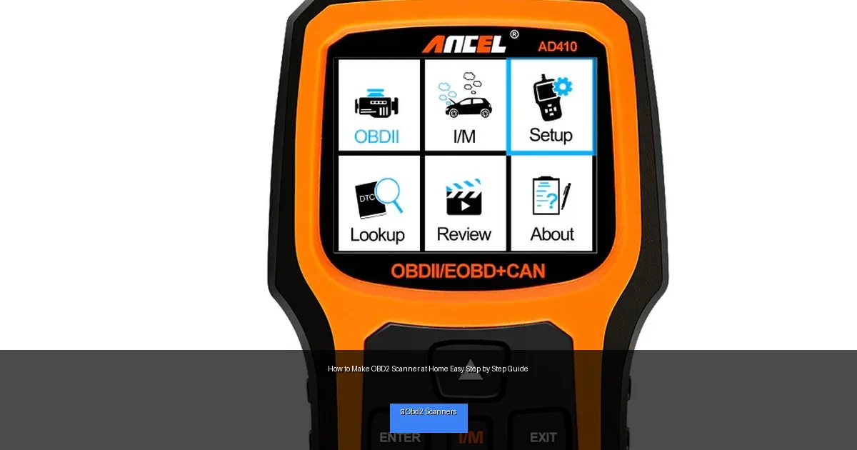
Visual guide about How to Make OBD2 Scanner at Home Easy Step by Step Guide
Image source: ancel.com
Building your own scanner helps you:
- Understand how vehicle diagnostics work
- Save money compared to buying commercial scanners
- Customize features to fit your preferences
- Gain hands-on electronics and programming experience
What You Will Need
Before starting, gather the following components:
- Microcontroller: Arduino Uno or similar (Arduino Nano is a good compact option)
- OBD2 Connector: Female OBD2 port connector to plug into your car
- OBD2 Interface Module: Like the ELM327 or a dedicated CAN transceiver (MCP2551)
- Wires and Jumper Cables: For connections
- Breadboard or PCB: To mount your circuit
- USB Cable: For programming the Arduino
- Computer: To write and upload code
- Optional: LCD display or Bluetooth module for output
Step 1: Understand the Basics of OBD2 Communication
OBD2 scanners talk to the car’s ECU (Engine Control Unit) using protocols such as CAN (Controller Area Network). The most common protocol is CAN bus. Your microcontroller will need to interface with this protocol to retrieve data.
The ELM327 IC is a popular choice because it converts OBD2 protocols into readable serial data.
Step 2: Connect the OBD2 Connector to Your Microcontroller
2.1 Identify Pinouts
The OBD2 port has 16 pins; the important ones for CAN communication are:
- Pin 6 – CAN High
- Pin 14 – CAN Low
- Pin 4 – Chassis Ground
- Pin 5 – Signal Ground
- Pin 16 – Battery Jump Starter”>Battery Power (+12V)
2.2 Wiring
Connect these pins to your microcontroller via the CAN transceiver module.
- Pin 16 to 12V power supply (through a voltage regulator to 5V if needed)
- Pin 4 and Pin 5 to ground
- Pin 6 and Pin 14 to CAN transceiver inputs
Be sure to double-check connections to avoid damaging your car’s ECU.
Step 3: Setup the CAN Transceiver Module
The CAN transceiver acts as a bridge between the car’s CAN bus and your microcontroller.
- Connect the CAN High and CAN Low lines from the OBD2 connector to the CAN transceiver module
- Connect the transceiver’s TX and RX pins to the Arduino’s serial communication pins (e.g., pins 10 and 11)
- Power the transceiver with 5V and ground
Step 4: Program Your Microcontroller
4.1 Install Arduino IDE
Download and install the Arduino IDE from the official website.
4.2 Add CAN Library
Install a CAN bus library such as “CAN” by Sandeep Mistry for Arduino. This library will help you communicate with the CAN bus.
4.3 Write the Code
Start with basic code to initialize CAN communication and read messages.
#include <CAN.h>

void setup() {
  Serial.begin(115200);
  while (!Serial);

  if (!CAN.begin(500E3)) {
    Serial.println("Starting CAN failed!");
    while (1);
  }
  Serial.println("CAN Initialized");
}

void loop() {
  int packetSize = CAN.parsePacket();

  if (packetSize) {
    Serial.print("Received packet with ID: ");
    Serial.println(CAN.packetId(), HEX);

    while (CAN.available()) {
      Serial.print((char)CAN.read());
    }
    Serial.println();
  }
}
This code initializes the CAN bus at 500 kbps and prints received data to the serial monitor.
Step 5: Test Your OBD2 Scanner
Plug the OBD2 connector into your vehicle’s OBD2 port, usually located under the dashboard.
- Open the Arduino serial monitor
- Turn the car ignition to ON but don’t start the engine
- Observe data being received
If you see packets and data, your scanner is working!
Step 6: Add Features and Improve
Once the basic scanner works, enhance it by:
- Decoding Diagnostic Trouble Codes (DTCs) into readable text
- Adding an LCD display to show codes without a PC
- Including a Bluetooth module to send data to your smartphone
- Logging data for analysis
Troubleshooting Tips
- No data received: Check your wiring and power connections.
- CAN initialization failed: Verify correct baud rate and CAN transceiver connections.
- Data garbled or unreadable: Ensure proper termination resistors (120 ohms) are present on CAN lines.
- Scanner freezes: Test with another vehicle or check code for bugs.
Safety Precautions
When working with your car’s electronics:
- Turn off the ignition before making connections
- Use the correct voltage levels to avoid short circuits
- Avoid damaging the OBD2 port pins
- Work in a dry, well-lit area
Conclusion
Making an OBD2 scanner at home is a rewarding project that combines electronics, programming, and automotive knowledge. By following this easy step-by-step guide, you have learned how to build a functional scanner that can read your vehicle’s diagnostic codes. With practice, you can expand its features and customize it further. This DIY approach saves money and deepens your understanding of car diagnostics. So, gather your parts and start building your own OBD2 scanner today!
🎥 Related Video: How to Use An OBD2 Code Reader in 3 Min! (Beginner DIY)
📺 SimpleDIYProjects
Diagnose your check engine light in 3 minutes! Learn how to use an OBD2 code reader to find and fix car issues like a pro. Perfect …